Fire Alarm Installation
Smoke and fire alarms are an important part of your home's safety plan and careful attention must be made to proper fire alarm installation and wiring. The information below will provide some basic guidelines for installing a fire alarm system in your new home.
Fire Alarm Placement
-Install the first alarm in the immediate area of the bedrooms. Try to protect the exit path as the bedrooms are usually farthest from the exit. If more than one sleeping area exists, locate additional alarms in each sleeping area.
-Install additional fire alarms to protect any stairway as stairways act like chimneys for smoke and heat.
-Install at least one fire alarm on every floor level.
-Install a fire alarm in every bedroom
-Install a fire alarm in every room where electrical appliances are operated (i.e. portable heaters or humidifiers).
-Install a fire alarm in every room where someone sleeps with the door closed. The closed door may prevent the alarm from waking the sleeper.
-Smoke, heat, and combustion products rise to the ceiling and spread horizontally. Mounting the smoke alarm on the ceiling in the center of the room places it closest to all points in the room. Ceiling mounting is preferred in ordinary residential construction.
-When mounting a fire alarm on the ceiling, locate it at a minimum of 4” (10 cm) from the side wall (see Diagram A).
-When mounting a fire alarm on the wall, use an inside wall with the top edge of the alarm at a minimum of 4” (10 cm) and a maximum of 12” (30.5 cm) below the ceiling (see Diagram A).
-Put fire alarms at both ends of a bedroom hallway or large room if the hallway or room is more than 30 feet long.
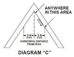
-When Fire Alarm Installation is on sloped, peaked or cathedral ceilings at or within 3ft of the highest point (measured horizontally). NFPA 72 states: “Smoke alarms in rooms with ceiling slopes greater than 1 foot in 8 feet horizontally shall be located on the high side of the room.” NFPA 72 states: “A row of detectors shall be spaced and located within 3 ft of the peak of the ceiling measured horizontally” (see diagram “C”).
Examples of Fire Alarm Placement in a House
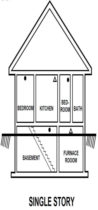
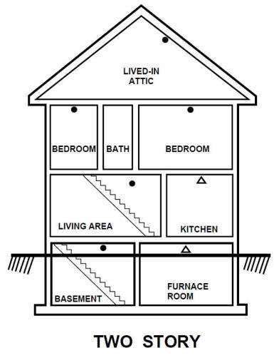
*Triangles indicate recommended placement of false-alarm protected devices such as photoeletric fire alarms.
Fire Alarm Installation - Locations to Avoid
-In the garage. Products of combustion are present when you start your automobile.
-Less than 4” from the peak of an “A” frame type ceiling.
-In an area where the temperature may fall below 40ºF or rise above 100ºF.
-In dusty areas. Dust particles may cause nuisance alarm or failure to alarm.
-In very humid areas. Moisture or steam can cause nuisance alarms.
-In insect-infested areas.
-Fire alarms should not be installed within 3 ft of the following: the door to a kitchen, the door to a bathroom containing a tub or shower, forced air ducts used for heating or cooling, ceiling or whole house ventilating fans, or other high air flow areas.
-Kitchens. Normal cooking may cause nuisance alarms. If a kitchen fire alarm is desired, it should have an alarm silence feature or be a photoelectric type.
Cooking pancakes can often set off fire alarms if they are too close to the stove.
-Near fluorescent lights. Electronic “noise” may cause nuisance alarms.
Fire Alarm Installation - Wiring
-Fire alarms should be installed on a U.L. listed or recognized junction box (standard 120V electrical boxes work fine)
-Fire alarms require 120 VAC supplied from a non-switchable circuit which is protected by an Arc-Fault Circuit Interrupter (AFCI) circuit breaker. The AFCI is required as this circuit provides outlets in bedrooms.
-For fire alarms that are used as single station, DO NOT CONNECT THE RED WIRE TO ANYTHING. Leave the red wire insulating cap in place to make certain that the red wire cannot contact any metal parts or the electrical box.
-When fire alarms are interconnected, all interconnected units must be powered from a single circuit.
-A maximum of 18-24 devices can typically be interconnected in a multiple station arrangement (see manufacturers instructions). The interconnect system should not exceed the NFPA interconnect limit of 12 fire alarms and/or 18 alarms total (smoke, heat, carbon monoxide, etc.) With 18 fire alarms interconnected, it is still possible to interconnect up to a total of 6 remote signaling devices and/or relay modules.
-The maximum wire run distance between the first and last unit in an interconnected system is typically 1000 feet (depends on manufacture and interconnecting wire gauge).
-Make certain fire alarms are wired to a continuous (non-switched) power line. NOTE: Use standard UL listed household wire (18 gauge or larger as required by local codes) available at all electrical supply stores and most hardware stores. Using 14/3 Romex is a good way to go and you can protect it with a standard 15A AFCI breaker.
Fire Alarm Wiring Diagram
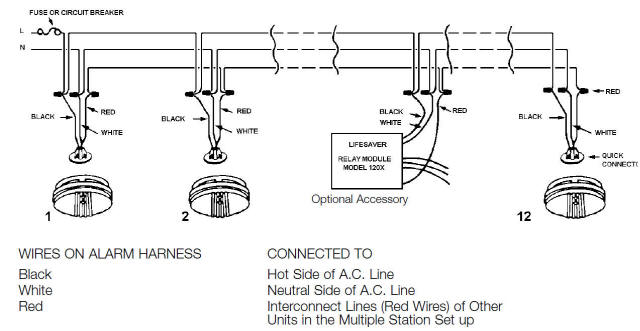
The red wire connecting the fire alarms is used to trigger all alarms if one detector goes off.
Ionization Detectors vs Photoelectric Fire Alarm Installation
There are two main types of smoke detectors: ionization detectors and photoelectric detectors. A smoke alarm uses one or both methods, sometimes plus a heat detector, to warn of a fire. The devices may be powered by a 9-volt battery, lithium battery, or 120-volt house wiring.
Ionization Detectors
Ionization detectors have an ionization chamber and a source of ionizing radiation. The source of ionizing radiation is a minute quantity of americium-241 (perhaps 1/5000th of a gram), which is a source of alpha particles (helium nuclei). The ionization chamber consists of two plates separated by about a centimeter. The battery applies a voltage to the plates, charging one plate positive and the other plate negative. Alpha particles constantly released by the americium knock electrons off of the atoms in the air, ionizing the oxygen and nitrogen atoms in the chamber. The positively-charged oxygen and nitrogen atoms are attracted to the negative plate and the electrons are attracted to the positive plate, generating a small, continuous electric current. When smoke enters the ionization chamber, the smoke particles attach to the ions and neutralize them, so they do not reach the plate. The drop in current between the plates triggers the alarm.
Photoelectric Detectors
In one type of photoelectric device, smoke can block a light beam. In this case, the reduction in light reaching a photocell sets off the alarm. In the most common type of photoelectric unit, however, light is scattered by smoke particles onto a photocell, initiating an alarm. In this type of detector there is a T-shaped chamber with a light-emitting diode (LED) that shoots a beam of light across the horizontal bar of the T. A photocell, positioned at the bottom of the vertical base of the T, generates a current when it is exposed to light. Under smoke-free conditions, the light beam crosses the top of the T in an uninterrupted straight line, not striking the photocell positioned at a right angle below the beam. When smoke is present, the light is scattered by smoke particles, and some of the light is directed down the vertical part of the T to strike the photocell. When sufficient light hits the cell, the current triggers the alarm.
Which Fire Alarm is Better?
Both ionization and photoelectric detectors are effective smoke sensors. Both types of smoke detectors must pass the same test to be certified as UL smoke detectors. Ionization detectors respond more quickly to flaming fires with smaller combustion particles; photoelectric detectors respond more quickly to smoldering fires. In either type of detector, steam or high humidity can lead to condensation on the circuit board and sensor, causing the alarm to sound. Ionization detectors are less expensive than photoelectric detectors, but some users purposely disable them because they are more likely to sound an alarm from normal cooking due to their sensitivity to minute smoke particles. However, ionization detectors have a degree of built-in security not inherent to photoelectric detectors. When the battery starts to fail in an ionization detector, the ion current falls and the alarm sounds, warning that it is time to change the battery before the detector becomes ineffective. Back-up batteries may be used for photoelectric detectors.
Residential Electrical Guidelines and Codes
Rough-In Electrical and Pulling Cable
Common Electrical Wiring Diagrams
Wire Gauge and Voltage Drop Calculator
NEC Reference Tables (2011, 2008, 2005, 2002, and 1999)
Sizing Your Electrical Service
Electrical - Main Service Line Installation
Click the icons below to get our NEC® compliant Electrical Calc Elite or Electric Toolkit for Android and iOS. The Electrical Calc Elite is designed to solve many of your common code-based electrical calculations like wire sizes, voltage drop, conduit sizing, etc. The Electric Toolkit provides some basic electrical calculations, wiring diagrams (similar to those found on this website), and other electrical reference data.