STEP 2: Designing a Solar Power System
There are tons of resources available online for designing your solar system. This includes deciding how many panels you need, what type of inverters to use, proper tilt angles, etc. For our cabin we kept the design as simple as possible. We had three different roof pitches that all faced due south. We wanted as many panels as we could get on the roof since all of our cabin appliances were electric (geothermal heating/cooling, lights, stove, fridge, two washers, two driers, two on-demand electric water heaters, and hot tub). We assumed no matter how many panels we installed it would be hard to completely zero out our electric bill.
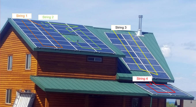
We ended up with 45 panels (Top Point, Model: JTM225-60P, 225W) and two string inverters (SMA Sunnyboy 6000TL-US and ABB Power One PVI-3.6-TL-OUTD) which both have 96-98% efficiency and dual input Max Power Point Tracking (MPPT). With this setup we used 4 independent solar strings (outlined in the figure above) on the rooftop which means if one string was shaded or covered by snow it wouldn't affect the others. Having the 3 different pitches on our roof meant there would be times one string might get shaded so it made sense to have a few different strings. A higher end solar system might use microinverters on each panel or power optimizers which allow you to monitor and utilize power on a per panel basis. These more expensive inverters have their advantages such as if a single panel gets shaded you can still utilize the other 10+ panels in the string with little or no impact on unshaded panels. On a string inverter if one panel gets shaded the entire string is impacted.
When we originally built our cabin we ran a 4" conduit from the attic to the mechanical room in the basement just in case we had wires or cables we needed to run in the future. That turned out to be very handy for this solar project. For strings 1, 2, and 3 we ran 10AWG PV wire into the attic through the ridge vent on the metal roof then into electrical junction boxes in the attic. For string 4 we took 10AWG PV wire into the attic through the soffit of the steeper roof section shown above. From the 4 junction boxes in the attic we ran 10AWG THWN conductors down the conduit to the mechanical room then into the garage where the inverters were mounted. We also ran ground conductors from each string of panels to the inverters and breaker panel in the basement. As an additional safety measure it is recommended if not required in many areas to ground all panels with a 6 or 8 AWG bare copper wire to an earth ground rod. This prevents hazardous situations where a solar panel or wiring fault might energize the mounting rails or outside metal of the panels. As an added safety measure, solar inverters sold in the USA are required to include DC GFI (Ground Fault Protection) per the NEC which should produce a fault on the inverter and let you know you have stray current from your solar array going to ground somewhere. This is a safety hazard from an electrical shock and fire perspective.
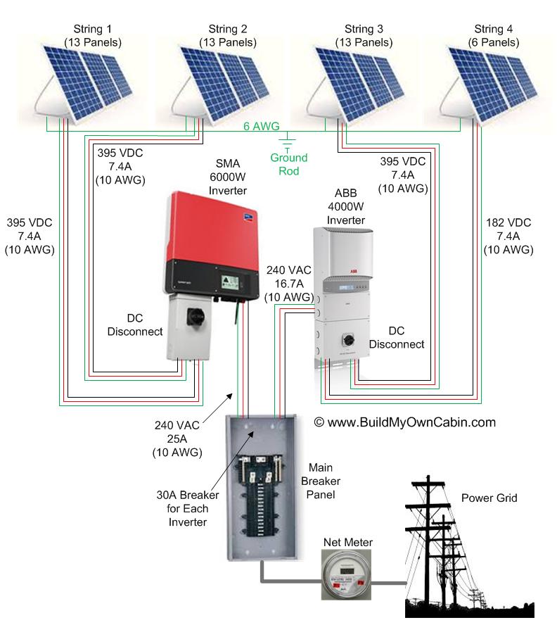
The figure above shows a basic wiring diagram of our grid-tie solar power system. Its very simple, divide the solar panels into several strings to match the inverter's voltage and current capacity. At maximum power, each of our solar panels can product 30.36V and 7.41A. Since the solar panels are wired in series the voltage adds but current is the same through the entire string of panels. Each solar inverter accepts two strings of solar panels with voltage from the panels being DC. It then converts this to AC power which is tied directly into your breaker panel with a standard breaker. The inverters have smarts to detect and produce an AC signal that is in phase and at the correct voltage to make feeding your household power grid possible. If the inverters produced power out of phase with the grid, like a gas generator for example, breakers would immediately pop and things would never work. Luckily today's inverters take care of all of this and all you have to worry about is making a few simple connections from the solar panels to inverters and from inverters to the main breaker panel.
The last piece required is for the power company to replace your current electric meter with a Net Meter. These meters measure power in both directions so if its night time and you are using power from the grid is works like a regular meter. In the day however there might be times when the solar power being generated exceeds what is being consumed in the house so you are feeding excess power back to the grid and the Net meter measures that and gives you credit. Many states, including Utah, allow the energy credits to be carried forward for up to a year so times of the year like Spring and Fall where you produce extra power can be carried forward and used to cover the Summer and Winter extremes where you might use more than you produce.
STEP 1: Solar Power - Do the numbers make sense?
STEP 2: Designing Your Own Solar Power System
STEP 3: Installing Solar Panels on Metal Roof
STEP 4: Connecting Solar Inverters