Low-Voltage Wiring
The follow sections will walk you through the essentials of installing low-voltage wiring in your house. We'll start with Ethernet and Coax wiring which is very simple to install and really should not be skipped in any modern home....even if you think you'll never use them!
Ethernet or Computer Network Wiring
Even if you think you'll never used a hard-wired network in you house because you prefer wireless networks you should still install the cable if you have the walls open and available. Wired connections are more secure, more reliable, and faster in most cases than any wireless options available. Having low-voltage wiring is expected in new homes today and can negatively or positively affect home appraisals.
I recommend that you run a minimum one data port to each bedroom, TV location, phone jack, and other places you may have a computer. You'll never regret running too many. All network cables are run point-to-point without any splices. These are commonly called home-runs in the industry as you are running from the destination port all to way home to your mechanical or control room where everything gets terminated. I strongly recommend running two cable runs to each location. You may chose to only terminate one at the wall jack and leave the other in the box for redundancy. It at least gives you the option to two ports if you ever need.
Residential Network Cable Options
CAT5 vs CAT6
Until recently CAT5 was quite common in residential network wiring. Many in the industry have transitioned to CAT6 for a little better performance and very little cost increase. CAT5E is commonly rated to 100MHz bandwidth whereas CAT6 is rated up to 250MHz. CAT6 has less insertion loss, less near end crosstalk, less return loss....all advantages in terms of signal quality. These improvement provide higher signal-to-noise ratio which gives you a high quality data line. CAT6 is made to support Gigabit Ethernet networks which are replacing the 10/100 MB networks of yesterday. You'll see CAT5E manufacturers claim to support Gigabit ENET as well but just keep in mind you will not have the same transmission performance resulting in increased re-transmissions of lost or corrupted data packets if your lines are in a noisy environment. You'll have to be more careful running your lines next to your high voltage lines or other sources of noise. CAT6 cabling is backwards compatible with CAT5 networks so there really is no reason not to use it. In fact 80 to 90% of new installations now use CAT6 instead of CAT5 cabling.
Cost of CAT6 vs CAT5 Cable
Here's a great place to purchase low-voltage wiring and terminations. Check www.MonoPrice.com You may be asking yourself if the monoprice products are really up to par with others and the answer is yes. I've worked with folks that install this stuff for a living in both residential and commercial applications and they go through this monoprice cable by the pallet. Here's a little price comparison between CAT5E and CAT6 at the time of writing this:
1000ft CAT6 - $95.98 (monoprice), $139.00 (Home Depot)
1000ft CAT5E - $73.92 (monoprice)
CAT5E keystone jack - $1.10 (monoprice), $4.91 (Home Depot)
CAT6 keystone jack - $1.43 (monoprice)
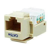
Residential Network Cable Install Summary
In summary, run two CAT6 cables from each data port box in your house to the control room. In the rooms you terminate to the keystone jacks like the one shown below. Make sure you select the tool-less keystones unless you have a punchdown tool. Follow the color-coding located on each keystone jack and match them with the colored wires in your CAT6 cable. There are two options for terminating network cables, T568B and T568A. Both will be shown on the directions of your keystone jack. T568B is the most common of the two in the US. Just be sure you stay consistent with all terminations, both in the rooms and in the control room where the other end is terminated. On a side note, you can use CAT6 cable for you phone as well. You just terminate 4 wires to your phone jack and then in your control room terminate to your phone block. CAT5 and CAT6 wiring should not be run parallel to electrical wires. Cross electrical wires at 90 degrees with your low-voltage wiring if possible.
CAT5 and CAT6 Wiring Diagrams
Ethernet Cable Pinout (T568B)
| RJ45 Pin # | Wire Color (T568B) |
Wire Diagram (T568B) |
10Base-T Signal 100Base-TX Signal |
1000Base-T Signal |
|---|---|---|---|---|
| 1 | White/Orange |
 |
Transmit+ | BI_DA+ |
| 2 | Orange |
 |
Transmit- | BI_DA- |
| 3 | White/Green |
 |
Receive+ | BI_DB+ |
| 4 | Blue |
 |
Unused | BI_DC+ |
| 5 | White/Blue |
 |
Unused | BI_DC- |
| 6 | Green |
 |
Receive- | BI_DB- |
| 7 | White/Brown |
 |
Unused | BI_DD+ |
| 8 | Brown |
 |
Unused | BI_DD- |
Ethernet Cable Pinout (T568A)
| RJ45 Pin # | Wire Color (T568A) |
Wire Diagram (T568A) |
10Base-T Signal 100Base-TX Signal |
1000Base-T Signal |
|---|---|---|---|---|
| 1 | White/Green |
|
Transmit+ | BI_DA+ |
| 2 | Green |
|
Transmit- | BI_DA- |
| 3 | White/Orange |
|
Receive+ | BI_DB+ |
| 4 | Blue |
|
Unused | BI_DC+ |
| 5 | White/Blue |
|
Unused | BI_DC- |
| 6 | Orange |
|
Receive- | BI_DB- |
| 7 | White/Brown |
|
Unused | BI_DD+ |
| 8 | Brown |
|
Unused | BI_DD- |
Power Over Ethernet (PoE)
Power over Ethernet has been implemented in many variations before IEEE standardized 802.3af. 802.3af specifies the ability to supply an endpoint with 48V DC at up 350mA or 16.8W. The endpoint must be capable of receiving power on either the data pairs [Mode A] (often called phantom power) or the unused pairs [Mode B] in 100Base-TX. PoE can be used with any ethernet configuration, including 10Base-T, 100Base-TX and 1000Base-T. Power is only supplied when a valid PoE endpoint is detected by using a low voltage probe to look for the PoE signature on the endpoint. PoE power is typically supplied in one of two ways, either the host ethernet switch provides the power, or a "midspan" device is plugged in between the switch and endpoints and supplies the power. No special cabling is required.
| RJ45 Pin # | Wire Color (T568A) |
Wire Diagram (T568A) |
10Base-T Signal 100Base-TX Signal |
PoE |
|---|---|---|---|---|
| 1 | White/Green |
|
Transmit+ | Mode A + |
| 2 | Green |
|
Transmit- | Mode A + |
| 3 | White/Orange |
|
Receive+ | Mode A - |
| 4 | Blue |
|
Unused | Mode B + |
| 5 | White/Blue |
|
Unused | Mode B + |
| 6 | Orange |
|
Receive- | Mode A - |
| 7 | White/Brown |
|
Unused | Mode B - |
| 8 | Brown |
|
Unused | Mode B - |
Splicing Ethernet Cable
Splicing a run of CAT5 or CAT6 Ethernet cable is liable to cause trouble. Ethernet cable is not like current-carrying wires which can be spliced easily. Without getting deeper into electrical theory, splices on Ethernet cable, especially Gigabit Ethernet, is very detrimental to the signal integrity of your cable. Impedance mismatches and reflections will occur at the point of a splice which can make a spliced cable unlikely to work well or even at all. Even if it seems to work, you are likely getting more retransmissions than normal which will hurt performance. Many people have tried splicing CAT5 by stripping the ends and using some electrical tape but at high data rates you will have signal degradation. You may get 10/100 Ethernet to work but forget it for Gigabit Ethernet. If you have the option to run a whole new cable do it. If you've severed a cable in a finished home and have no other options, your best bet is to using a crimper and plug and basically terminate the cables and plug them together. Crimpers are handy for making your own patch cables and tool-less plug terminations are easy to come by as well. It still won't be as good as a new cable but if you have no other choice, it can work.
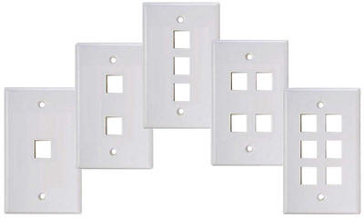
Keystone Jack Wall Plates
Keystone jacks can be purchased in a variety of different colors. Wallplates also come in a variety of options from single to six ports per plate as shown below.
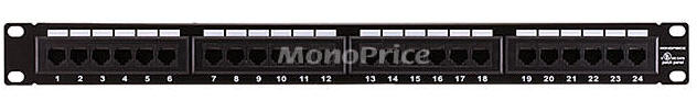
All low-voltage wiring in you house will typically be run to your mechanical room or control room where your network routers and patch panels are setup. Patch panels are typically used to terminate each CAT6 cable at which point you can label and manage the mess of cables you'll have. Here's a 24 port patch panel from monoprice:
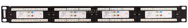
On the back of the patch panel you see the color-coded marking to for each wire. Again make sure you use the T568B markings if that's what you used on your keystone jacks.
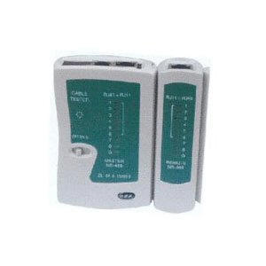
Once you've terminated both sides of your CAT6 cables you are done. From there you can use patch cables, purchased for pennies at monoprice, to plug between your patch panel and Ethernet router and also from your keystone jack to your PC. If you've terminated everything properly it should work great. If you are installing for others and need to make sure all connections are perfect when you leave you can even purchase a network cable checker for around $20 (see below).
Coax Cable Options
For wiring TVs, CATV, antennas, or satellites you'll need to run coax cable. This is the second half of your low-voltage wiring project once the Ethernet is taken care of. Coax standards include RG-59, RG-6, and RG-11. RG-59 used to be more common but now most people recommend a quad shielded RG-6 for residential applications. 1000ft of quad shield RG-6 is about $60 at monoprice. RG-11 is lower loss but more expensive and not common for residential use.
I would recommend one or two coax cables per bedroom, two or three to each TV location, three to four to your attic for an attic antenna or Dish Network. Make sure these runs are long enough to the attic to reach all the way to your dish location without having to splice them. A little planning ahead in this area goes a long ways and prevents having to have the Dish Network man run cables all over the outside of your house. You should also plan to run a couple cables from your main control room to the service entrance to your house for cable TV connections. Another idea I've used before to future-proof your low voltage wiring is to run a 3 or 4" conduit from your mechanical room to your attic. You'll want to stuff some insulation in each end so you don't get a draft of cold air but this conduit is a life-saver if you ever need to make any new low-voltage runs to your attic.
Terminations for coax are called F connectors. Some of the best connectors are compression connectors which require a compression tool. You can pick one of these up at Home Depot or at various places online. Make sure the F fittings you purchase match the coax cable type that you've installed (i.e. RG-6U quad shield). The compression fittings will come with simple instructions to follow for stripping the shield and performing the terminations or you can follow the installation guide below.
Coax Connector Installation Guide
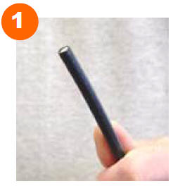
Cut the coax cable as straight as possible using a sharp cutting tool. There are special tools designed specifically for cutting coax cable and they work best but if not do you best to make a straight cut. The sharper the tool the better to reduce deforming the dielectric of the cable which can degrade cable performance. Be careful not to cut the cable at an angle.
Use a cable stripper designed to expose 1/4" of center conductor and 1/4" of dielectric. This is standard for most F type coax connectors but be sure to double check the instructions on your particular fittings. You should stay away from carpet knives, pocket knives, and razor blades for stripping coax cables as there is a good chance you will accidently cut through the cable braid and degrade your connection.
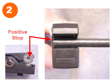
To prepare or strip the cable, rotate the stripper three rotations around the cable then reverse for three additional rotations. Be careful not to cut through the cable braid.
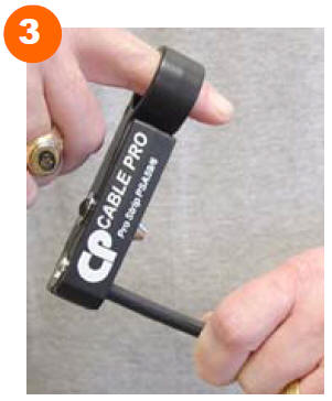
With the stripper in the closed position, pull the cable out of the tool jaws. The will properly remove the cut materials.
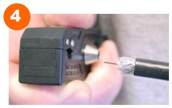
Use your fingers to carefully pull the braid back from the dielectric leaving the foil in place. For quad shield cable, pull back the outer layer of braid, remove the outer layer of foil, then pull back the inner layer of braid. Leave the inner layer of foil around the dielectric.
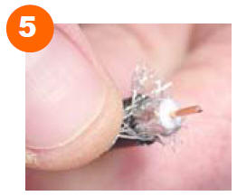
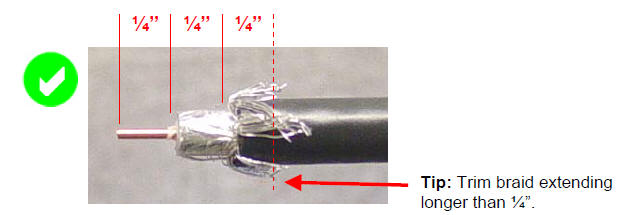
A properly prepared cable will have 1/4" of bare center conductor, 1/4" of foil covered dielectric, and 1/4" of braid as shown below.
Installing Coax Compression Fittings
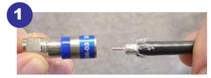
Grip the connector at the nut or between the nut and compression die. Insert prepared cable into the connector and push firmly.
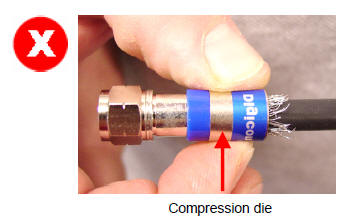
Do not grip the connector by the compression die as shown below. Moving the die can cause the die to separate from the ferrule.
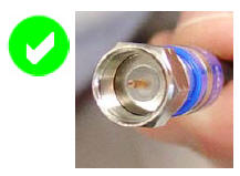
When the connector is properly applied, the dielectric should be flush with the internal base of the connector and the center conductor should protrude slightly form the end of the connector as shown below.
Lift the compression tool handle to retract the plunger.
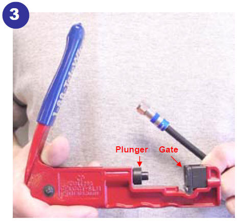
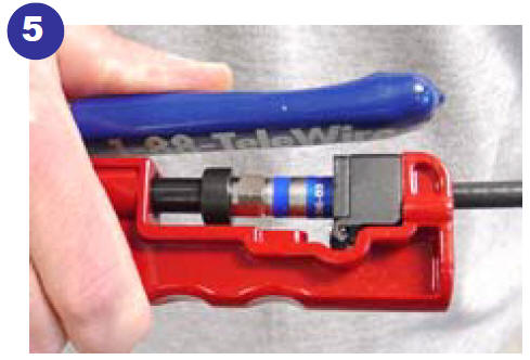
Seat the nut of the connector on the head of the plunger and lower the cable into the groove of the tool. Your tool may look different than this one but the operation will be similar.
You should get a compression tool made for the brand of compression fittings that you purchase to ensure proper compression and mating.
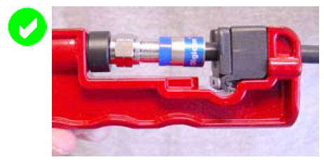
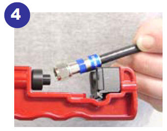
Squeeze the tool handle to compress the connector onto the cable.
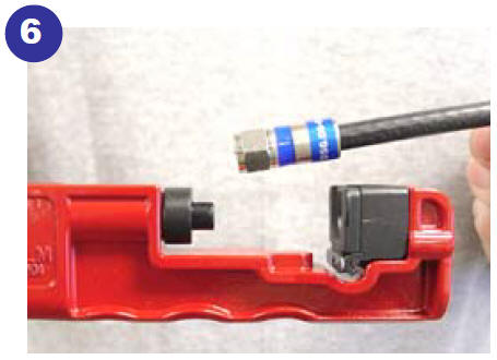
Lift the tool handle to retract the plunger and remove the finished connector assembly form the tool.
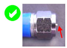
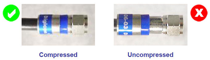
A properly compressed or uncompressed fitting will look similar to the figures below.
Coax Installation Summary
Once you have terminated both sides of your coax cables, using the instructions above, you can use F-type keystone jacks and wallplates for your rooms. The other ends of your coax cables can plug directly into coax splitters or hubs in your main control room. That's it for low voltage wiring!
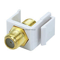 F-Type
Keystone Jack
F-Type
Keystone Jack
Residential Electrical Guidelines and Codes
Rough-In Electrical and Pulling Cable
Common Electrical Wiring Diagrams
Wire Gauge and Voltage Drop Calculator
NEC Reference Tables (2011, 2008, 2005, 2002, and 1999)
Sizing Your Electrical Service
Electrical - Main Service Line Installation
Click the icons below to get our NEC® compliant Electrical Calc Elite or Electric Toolkit for Android and iOS. The Electrical Calc Elite is designed to solve many of your common code-based electrical calculations like wire sizes, voltage drop, conduit sizing, etc. The Electric Toolkit provides some basic electrical calculations, wiring diagrams (similar to those found on this website), and other electrical reference data.