CAT-5 Ethernet HDMI Firewire USB Cable Pinouts
This webpage illustrates many of the most common household cable pinouts. These include CAT-5 Ethernet, HDMI, Firewire, USB and DVI to name a few. It also covers high voltage receptacle pinouts commonly used in your home.
Ethernet cables, especially Cat5e or Cat6, are considered one of the best choices for wiring home security cameras.
Ethernet Cable Pinout
| Pin # (T568B) |
Wire Diagram (T568B) |
10Base-T 100Base-TX |
1000Base-T |
|---|---|---|---|
| 1 |
 |
Transmit+ | BI_DA+ |
| 2 |
 |
Transmit- | BI_DA- |
| 3 |
 |
Receive+ | BI_DB+ |
| 4 |
 |
Unused | BI_DC+ |
| 5 |
 |
Unused | BI_DC- |
| 6 |
 |
Receive- | BI_DB- |
| 7 |
 |
Unused | BI_DD+ |
| 8 |
 |
Unused | BI_DD- |
| Pin # (T568A) |
Wire Diagram (T568A) |
10Base-T 100Base-TX |
1000Base-T |
|---|---|---|---|
| 1 |
|
Transmit+ | BI_DA+ |
| 2 |
|
Transmit- | BI_DA- |
| 3 |
|
Receive+ | BI_DB+ |
| 4 |
|
Unused | BI_DC+ |
| 5 |
|
Unused | BI_DC- |
| 6 |
|
Receive- | BI_DB- |
| 7 |
|
Unused | BI_DD+ |
| 8 |
|
Unused | BI_DD- |
USB Cable Pinout
Plugs Receptacles Series A
Series B
Mini-USB Series A
Mini-USB
Series B
Standard USB Cable Pinouts
| PIN | Function |
| 1 | V BUS (+5V) |
| 2 | D- |
| 3 | D+ |
| 4 | Ground |
Mini-USB Cable Pinouts
| PIN | Function |
| 1 | V BUS (+5V) |
| 2 | D- |
| 3 | D+ |
| 4 | ID |
| 5 | Ground |
HDMI Cable Pinout
| PIN | Function |
| 1 | TMDS Data2+ |
| 2 | TMDS Data2 Shield |
| 3 | TMDS Data2- |
| 4 | TMDS Data1+ |
| 5 | TMDS Data1 Shield |
| 6 | TMDS Data1- |
| 7 | TMDS Data0+ |
| 8 | TMDS Data0 Shield |
| 9 | TMDS Data0- |
| 10 | TMDS Clock+ |
| 11 | TMDS Clock Shield |
| 12 | TMDS Clock- |
| 13 | CEC |
| 14 | Reserved |
| 15 | SCL |
| 16 | SDA |
| 17 | DDC/CEC Ground |
| 18 | +5 V Power |
| 19 | Hot Plug Detect |
DVI Cable Pinout

| PIN | Function |
| 1 | T.M.D.S DATA 2- |
| 2 | T.M.D.S DATA 2+ |
| 3 | T.M.D.S DATA 2/4 SHIELD |
| 4 | T.M.D.S DATA 4- |
| 5 | T.M.D.S DATA 4+ |
| 6 | DDC CLOCK |
| 7 | DDC DATA |
| 8 | ANALOG VERT. SYNC |
| 9 | T.M.D.S DATA 1- |
| 10 | T.M.D.S DATA 1+ |
| 11 | T.M.D.S DATA 1/3 SHIELD |
| 12 | T.M.D.S DATA 3- |
| 13 | T.M.D.S DATA 3+ |
| 14 | +5V POWER |
| 15 | GND |
| 16 | HOT PLUG DETECT |
| 17 | T.M.D.S DATA 0- |
| 18 | T.M.D.S DATA 0+ |
| 19 | T.M.D.S DATA 0/5 SHIELD |
| 20 | T.M.D.S DATA 5- |
| 21 | T.M.D.S DATA 5+ |
| 22 | T.M.D.S CLOCK SHIELD |
| 23 | T.M.D.S CLOCK+ |
| 24 | T.M.D.S CLOCK- |
| C1 | ANALOG RED |
| C2 | ANALOG GREEN |
| C3 | ANALOG BLUE |
| C4 | ANALOG HORZ SYNC |
| C5 | ANALOG GROUND |
Dual Link versus Single Link DVI Pinouts
Component Video Cable Pinout
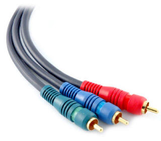
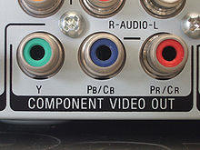
| Color | Signal | Function |
| Green | Y | Carries luma (brightness or luminance) and synchronization (sync) information |
| Blue | PB | Carries the difference between blue and luma (B − Y) |
| Red | BR | Carries the difference between red and luma (R − Y) |
The designation for analog component video signals. The "Y," "Pb" and "Pr" are sets of three inputs or outputs on video equipment and TVs. The three cables used in a YPbPr connection represent higher quality than the single-wire composite cable commonly used to hook up video equipment, because the brightness and color components of the signal are maintained separately. The YPbPr signals are derived from the red, green and blue (RGB) colors captured by a scanner or digital camera, and RGB is converted into brightness and two color difference signals (B-Y and R-Y) for TV/video.
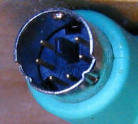
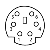
S-Video Pinout
| PIN | Signal | Function |
| 1 | GND | Ground (Y) |
| 2 | GND | Ground (C) |
| 3 | Y | Intensity (Luminance) |
| 4 | C | Color (Chrominance) |
RCA (Composite) Pinout
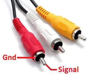
| Color | Function |
| Yellow | Composite Video Signal |
| White | Stereo Audio (Left) |
| Red | Stereo Audio (Right) |
PS/2 Cable Pinout
| PIN | Function |
| 1 | Keyboard/Mouse Data |
| 2 | Unused |
| 3 | GND |
| 4 | VCC (+5V) |
| 5 | Keyboard/Mouse Clock |
| 6 | Unused |
Firewire Cable Pinout
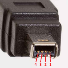
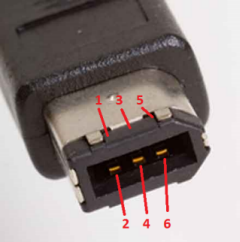
| 4-pin Connector | 6-pin Connector | Signal | Function |
| 1 | VCC | +30V unregulated DC | |
| 2 | GND | Ground | |
| 1 | 3 | TPB- | Twisted pair B |
| 2 | 4 | TPB+ | Twisted pair B |
| 3 | 5 | TPA- | Twisted pair A |
| 4 | 6 | TPA+ | Twisted pair A |
VGA Cable Pinouts
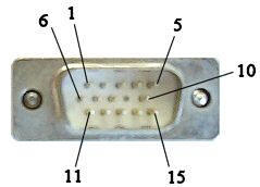
| PIN | Function |
| 1 | Red |
| 2 | Green |
| 3 | Blue |
| 4 | No Connect |
| 5 | Ground |
| 6 | Ground |
| 7 | Ground |
| 8 | Ground |
| 9 | No Connect |
| 10 | Ground |
| 11 | No Connect |
| 12 | DDC DAT |
| 13 | Horiz Sync |
| 14 | Vert Sync |
| 15 | DDC Clock |
Serial Cable Pinout
| PIN | Function |
| 1 | Data Carrier Detect (DCD) |
| 2 | Receive Data (RXD) |
| 3 | Transmit Data (TXD) |
| 4 | Data Termainl Ready (DTR) |
| 5 | Ground |
| 6 | Data Set Ready (DSR) |
| 7 | Request to Send (RTS) |
| 8 | Clear to Send (CTS) |
| 9 | Ringing Indicator (RI) |
Parallel (LPT) Port Pinout
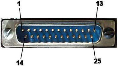
| PIN | Function |
| 1 | Strobe |
| 2 | Data Bit 0 |
| 3 | Data Bit 1 |
| 4 | Data Bit 2 |
| 5 | Data Bit 3 |
| 6 | Data Bit 4 |
| 7 | Data Bit 5 |
| 8 | Data Bit 6 |
| 9 | Data Bit 7 |
| 10 | Acknowledge (ACK) |
| 11 | Busy |
| 12 | Paper End (PE) |
| 13 | Select (SEL) |
| 14 | Autofeed (AUTOFD) |
| 15 | Error |
| 16 | Initialize (INIT) |
| 17 | Select In (SELIN) |
| 18 | Signal Ground (GND) |
| 19 | Signal Ground (GND) |
| 20 | Signal Ground (GND) |
| 21 | Signal Ground (GND) |
| 22 | Signal Ground (GND) |
| 23 | Signal Ground (GND) |
| 24 | Signal Ground (GND) |
| 25 | Signal Ground (GND) |
NEMA Plugs and Receptacles
Locking Type NEMA Plugs and Receptacles
Common Electrical Wiring Diagrams
Frequently Asked Electrical Questions
Wire Gauge and Voltage Drop Calculator
Residential Electrical Guidelines and Codes
Rough-In Electrical and Pulling Cable
Sizing Your Electrical Service
Electrical - Main Service Line Installation
Click the icons below to get our NEC® compliant Electrical Calc Elite or Electric Toolkit for Android and iOS. The Electrical Calc Elite is designed to solve many of your common code-based electrical calculations like wire sizes, voltage drop, conduit sizing, etc. The Electric Toolkit provides some basic electrical calculations, wiring diagrams (similar to those found on this website), and other electrical reference data.