Copper Wire Resistance and Voltage Drop
AWG stands for "American Wire Gauge" and is a standardized wire gauge system used in the US since 1857 for diameters of round, nonferrous, electrically conducting wire. The cross-sectional area of a wire determines it's resistance and current-carrying capacity. The large the wire diameter, the less resistance it has to the flow of electrons, and the more current it can carry without overheating. The table below list copper wire resistance for various gauges of copper wire. These should be used as a rule of thumb as there are other factors that play into the current ratings of wire including ambient temperature, insulation temperature limit, air convection, etc. You should consult the National Electrical Code (NEC) for specific guidelines.
AWG Wire Sizes and Resistance
| AWG gauge | Conductor Diameter Inches | Conductor Diameter mm | Ohms per 1000 ft. | ||
| 0000 | 0.46 | 11.684 | 0.049 | ||
| 000 | 0.4096 | 10.40384 | 0.0618 | ||
| 00 | 0.3648 | 9.26592 | 0.0779 | ||
| 0 | 0.3249 | 8.25246 | 0.0983 | ||
| 1 | 0.2893 | 7.34822 | 0.1239 | ||
| 2 | 0.2576 | 6.54304 | 0.1563 | ||
| 3 | 0.2294 | 5.82676 | 0.197 | ||
| 4 | 0.2043 | 5.18922 | 0.2485 | ||
| 5 | 0.1819 | 4.62026 | 0.3133 | ||
| 6 | 0.162 | 4.1148 | 0.3951 | ||
| 7 | 0.1443 | 3.66522 | 0.4982 | ||
| 8 | 0.1285 | 3.2639 | 0.6282 | ||
| 9 | 0.1144 | 2.90576 | 0.7921 | ||
| 10 | 0.1019 | 2.58826 | 0.9989 | ||
| 11 | 0.0907 | 2.30378 | 1.26 | ||
| 12 | 0.0808 | 2.05232 | 1.588 | ||
| 13 | 0.072 | 1.8288 | 2.003 | ||
| 14 | 0.0641 | 1.62814 | 2.525 | ||
| 15 | 0.0571 | 1.45034 | 3.184 | ||
| 16 | 0.0508 | 1.29032 | 4.016 | ||
| 17 | 0.0453 | 1.15062 | 5.064 | ||
| 18 | 0.0403 | 1.02362 | 6.385 | ||
| 19 | 0.0359 | 0.91186 | 8.051 | ||
| 20 | 0.032 | 0.8128 | 10.15 | ||
| 21 | 0.0285 | 0.7239 | 12.8 | ||
| 22 | 0.0254 | 0.64516 | 16.14 | ||
| 23 | 0.0226 | 0.57404 | 20.36 | ||
| 24 | 0.0201 | 0.51054 | 25.67 | ||
| 25 | 0.0179 | 0.45466 | 32.37 | ||
| 26 | 0.0159 | 0.40386 | 40.81 | ||
| 27 | 0.0142 | 0.36068 | 51.47 | ||
| 28 | 0.0126 | 0.32004 | 64.9 | ||
| 29 | 0.0113 | 0.28702 | 81.83 | ||
| 30 | 0.01 | 0.254 | 103.2 | ||
| 31 | 0.0089 | 0.22606 | 130.1 | ||
| 32 | 0.008 | 0.2032 | 164.1 |
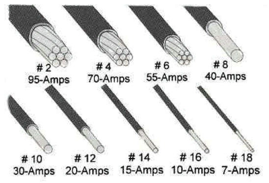
The diagram below shows many of the common copper wire sizes used when wiring a home. General ampacity ratings are listed as well but you should consult the tables below for more accurate ampacity ratings. This illustration is meant to show relative sizes of the common gauges of wire.
Common Copper Wire Sizes
This table provides the amperage rating for common insulated conductors including Romex. Insulated conductors should have the temp rating and type (i.e. THWN 75ºC) printed on the outside of the cable. You can then follow the chart below to see how much current you are allowed to put through the conductor. This table assumes not more than three conductors in a raceway or cable or earth (directly buried) and is based on ambient temperature of 30ºC (86ºF).
Ampacities of Insulated Conductors
| Size | Temperature Rating of Conductor | Size | |||||
| AWG | 60ºC | 75ºC | 90ºC | 60ºC | 75ºC | 90ºC | AWG |
| (140ºF) | (167ºF) | (194ºF) | (140ºF) | (167ºF) | (194ºF) | ||
| Types | Types | Types | Types | Types | Types | ||
|
T TW UF |
THW THWN XHHW USE |
RHH THHN XHHW |
T TW UF |
THW THWN XHHW USE |
RHH THHN XHHW |
||
| 0 | Copper | Aluminum | |||||
| 14 | 20 | 20 | 25 | ---- | ---- | ---- | ---- |
| 12 | 25 | 25 | 30 | 20 | 20 | 25 | 12 |
| 10 | 30 | 35 | 40 | 25 | 30 | 35 | 10 |
| 8 | 40 | 50 | 55 | 30 | 40 | 45 | 8 |
| 6 | 55 | 65 | 75 | 40 | 50 | 60 | 6 |
| 4 | 70 | 85 | 95 | 55 | 65 | 75 | 4 |
| 3 | 85 | 100 | 110 | 65 | 75 | 85 | 3 |
| 2 | 95 | 115 | 130 | 75 | 90 | 100 | 2 |
| 1 | 110 | 130 | 150 | 85 | 100 | 115 | 1 |
| 0 | 125 | 150 | 170 | 100 | 120 | 135 | 0 |
| 00 | 145 | 175 | 195 | 115 | 135 | 150 | 00 |
| 000 | 165 | 200 | 225 | 130 | 155 | 175 | 000 |
| 0000 | 195 | 230 | 260 | 150 | 180 | 205 | 0000 |
| 250 | 215 | 255 | 290 | 170 | 205 | 230 | 250 |
| 300 | 240 | 285 | 320 | 190 | 230 | 255 | 300 |
| 350 | 260 | 310 | 350 | 210 | 250 | 280 | 350 |
| 400 | 280 | 335 | 380 | 225 | 270 | 305 | 400 |
| 500 | 320 | 380 | 430 | 260 | 310 | 350 | 500 |
The table below provides the maximum number of THNN conductors that you can put in a given size conduit. Correction factors should be used if putting more than 3 conductors in a raceway.
Maximum Number of THNN Conductors in Conduit
| Conduit Size (inches) | ||||||||||||
| AWG | 1/2 | 3/4 | 1 | 1 1/4 | 1 1/2 | 2 | 2 1/2 | 3 | 3 1/2 | 4 | 5 | 6 |
| 14 | 13 | 24 | 39 | 69 | 94 | 154 | ||||||
| 12 | 10 | 18 | 29 | 51 | 70 | 114 | 164 | |||||
| 10 | 6 | 11 | 18 | 32 | 44 | 73 | 104 | 160 | ||||
| 8 | 3 | 5 | 9 | 16 | 22 | 36 | 51 | 51 | 106 | 136 | ||
| 6 | 1 | 4 | 6 | 11 | 15 | 26 | 37 | 37 | 76 | 98 | 154 | |
| 4 | 1 | 2 | 4 | 7 | 9 | 16 | 22 | 22 | 47 | 60 | 94 | 137 |
| 3 | 1 | 1 | 3 | 6 | 8 | 13 | 19 | 29 | 39 | 51 | 80 | 116 |
| 2 | 1 | 1 | 3 | 5 | 7 | 11 | 16 | 25 | 33 | 43 | 67 | 97 |
| 1 | 1 | 1 | 3 | 5 | 8 | 12 | 18 | 25 | 32 | 50 | 72 | |
| 0 | 1 | 1 | 3 | 4 | 7 | 10 | 15 | 21 | 27 | 42 | 61 | |
| 00 | 1 | 1 | 2 | 3 | 6 | 8 | 13 | 17 | 22 | 35 | 51 | |
| 000 | 1 | 1 | 1 | 3 | 5 | 7 | 11 | 14 | 18 | 29 | 42 | |
| 0000 | 1 | 1 | 1 | 2 | 4 | 6 | 9 | 12 | 15 | 24 | 35 | |
| 250 | 1 | 1 | 1 | 3 | 4 | 7 | 10 | 12 | 20 | 28 | ||
| 300 | 1 | 1 | 1 | 3 | 4 | 6 | 8 | 11 | 17 | 24 | ||
| 350 | 1 | 1 | 1 | 2 | 3 | 5 | 7 | 9 | 15 | 21 | ||
| 400 | 1 | 1 | 1 | 3 | 5 | 6 | 8 | 13 | 19 | |||
| 500 | 1 | 1 | 1 | 2 | 4 | 5 | 7 | 11 | 16 | |||
Ampacity Correction Factors for more than 3 conductors in Raceway
| No. Conductors | 4 to 6 | 7 to 9 | 10 to 20 | 21 to 30 | 31 to 40 |
| Factor | 0.8 | 0.7 | 0.5 | 0.45 | 0.4 |
Why do I need larger gauge wire to carry more current?
The larger the copper wire size the less resistance and hence the more current it can carry without over-heating. Resistance impedes to the flow of electrons and causes a voltage drop across the wire. You want to avoid voltage drops on your wiring as much as possible because they generate heat and wasted energy. The calculator below will help determine how much voltage drop you will get with a given copper wire and its associated resistance.
Voltage Drop Calculator
This calculator determines the voltage drop for an
aluminum or copper wire of any gauge. You
should generally target less than 3%
voltage drop in a given circuit. Wire resistances are
based on NEC 2008, Table 8 at 75oC.
|
Voltage Drop Calculator Download
The following Excel spreadsheet is a voltage drop calculator that is a little more advanced. It can be used to determine recommended wire gauges, maximum distances, or maximum amperage.
Voltage Drop Calc (.xls, 650KB)
Grounding Conductor Size Calculator
Common Electrical Wiring Diagrams
Frequently Asked Electrical Questions
Wire Gauge and Voltage Drop Calculator
NEC Reference Tables (2011, 2008, 2005, 2002, and 1999)
Residential Electrical Guidelines and Codes
Rough-In Electrical and Pulling Cable
Sizing Your Electrical Service
Electrical - Main Service Line Installation
Click the icons below to get our NEC® compliant Electrical Calc Elite or Electric Toolkit for Android and iOS. The Electrical Calc Elite is designed to solve many of your common code-based electrical calculations like wire sizes, voltage drop, conduit sizing, etc. The Electric Toolkit provides some basic electrical calculations, wiring diagrams (similar to those found on this website), and other electrical reference data.